The Precautions During The assembling Of Fuel Injection Pump
The Precautions During The Assembling Of Fuel Injection Pump
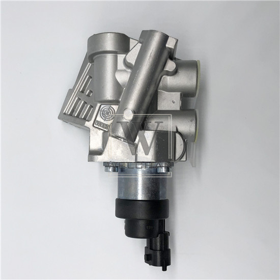
The assembling quality of fuel injection pump plays a decisive role in the difficulty of calibration and adjustment. Most of the faults and rework found in the verification are caused by poor assembling quality. Therefore, the assembling process should be carefully and repeatedly checked, and the defects found should not be left to be eliminated during the calibration.
·Special Tools Used For Dismounting And Assembling·
Before disassembling and assembling, clean and prepare the required tools, especially special tools. In the process of disassembling and assembling, open-ended wrench, ring wrench, socket wrench and various special tools must be used, and universal tools such as adjustable wrench shall not be used as much as possible. In particular, special tools shall be used as much as possible for tight fitting parts, and hammers, chisels and other tools that are easy to damage parts shall not be used.
·Notes And Key Points For Disassembling·
1. The disassembled parts shall be arranged in order according to the parts, so as to facilitate the number matching assembling during installation.
2. The fuel injection pump shall be disassembled on the special clamp to avoid the shell deformation. If it is disassembled on the vise, software such as copper strip must be installed on the jaw to avoid damage to parts. The clamping part shall not be on the fitting surface or mounting surface.
3. Keep the parts, tools and worktable clean at all times.
4. The precision coupling parts such as plunger, plunger sleeve, oil outlet valve and valve seat should be very careful in the process of disassembling, cleaning and storage. They should not collide or exchange with each other. They should be stored in pairs in clean diesel oil.
5. Before disassembling the fuel injection pump, the surface shall be cleaned with gasoline, kerosene or diesel oil, and the alkaline water shall not be used for cleaning.
6. Some parts requiring constant assembling position, such as gear bar, control arm and adjusting screw, should remember the original assembling position by marking when disassembling, so as to facilitate correct assembling.
·Basic Operation Points Of Assembling·
1. The plunger and the plunger sleeve are matched in sets and cannot be exchanged. Before installing the fuel injection pump body, check whether their models conform to the installed fuel injection pump. The plunger sleeve with the same height of adjusting roller drive component can have different plunger diameter. If the plunger diameter is installed incorrectly, it is impossible to reach the normal oil supply. The plunger with the same diameter is installed on the left or right side of the diesel engine according to the fuel injection pump, which is divided into "left engine" and "right engine". The chute of the plunger head is also divided into "left" and "right", which are used for "left machine" and "right machine". If it is installed incorrectly, it will cause the control lever to move in the direction of increasing oil supply, while the plunger will move in the direction of reducing oil supply, so the fuel injection pump cannot work. When replacing the new plunger and plunger sleeve, the method of comparing with the original core can be used to avoid mistakes.
2. When installing the oil outlet valve and valve seat, pay attention to the cleaning of the upper end face of the plunger sleeve and the lower end face of the oil outlet valve seat to make the joint face tight. If mechanical impurities are clamped in, when the plunger works, high-pressure oil will leak, so that the uniformity of oil supply quantity of each cylinder cannot be adjusted. There should be a little clearance between the inner diameter of the oil outlet valve gasket and the outer diameter of the oil outlet valve body. If it is too tight, after the oil outlet valve seat is compressed, the oil outlet valve seat will be deformed and there will be a risk of sticking the oil outlet valve. The outer diameter of the gasket shall not be too small, otherwise the seal is not tight, and low pressure oil will leak from the gap of the screw hole of the oil outlet valve pressing seat on the pump body. When screw in the compression seat of the oil outlet valve, the torque of 49 ~ 68, Sn and M is appropriate. If it is too tight, the plunger sleeve will be deformed and the plunger will be stuck in the plunger sleeve. When there is no torque wrench or lack of experience, tighten the compression seat of the oil outlet valve, and install the plunger into the plunger sleeve for test, if the plunger moves freely. If it is not smooth, it means that the torque is too large. Slowly loosen the compression seat of the oil outlet valve until it is suitable.
3. When installing the plunger, it shall be careful and accurate, and shall not touch the hair or be installed wrongly. After installation, it shall be able to move up, down, left and right freely. On the fuel injection pump of toothed rod type control mechanism, the mortise at the lower end of the plunger can be installed into the straight cutting groove of the control sleeve in both directions. Generally, the manufacturer has marked on the mortise at the lower end of the plunger, and the mark shall be upward during installation.
4. When the hole on the pump body is deformed or has burr, and the plunger sleeve cannot be inserted, reamer shall be used to ream the hole, so that the plunger sleeve can be installed slightly loosely.
5. When installing the camshaft, the rotation direction and injection sequence of the fuel injection pump shall be made clear before the pump body is installed. It is not allowed to install the camshaft reversely. The oil seals at both ends shall seal the lubricating oil in the pump body and shall not be installed wrongly. After the bearing blocks on both sides are installed, the camshaft shall rotate flexibly, and the axial clearance shall meet the specification requirements. If it is not suitable, it can be adjusted by adding or removing gasket.
6. After repairing and reassembling the roller drive parts, after the pump body is installed, when rotating the L-J dust shut "l camshaft, it shall move up and down flexibly without clamping. The height of the adjusting screw on it should be adjusted in advance, not too high, otherwise, the plunger and other parts will be squeezed out during the subsequent assembling and fastening process.
7. When installing the plunger spring, the upper and lower plunger spring seats shall not be installed reversely, otherwise the injection pump may be locally jammed. When installing the upper spring seat, check whether the adjusting ring gear has axial clearance. If the adjusting ring gear has been jacked, it means that the spring seat hole is worn, and the corresponding spring upper seat should be re equipped or a ring-shaped gasket should be added on the spring upper seat to ensure the flexible rotation of the adjusting ring gear. The steel wire retainer ring of the lower spring seat shall be cut and installed into the groove, without skew.
8. Before installing the adjusting gear ring, install the adjusting gear rod into the pump body and determine the installation position. When there is a marking mark on the adjusting gear rod, the marking shall be facing the end face of the pump housing. When there is a punch mark on the adjusting gear rod, align the punch with the adjusting gear rod bush on the pump body. Then keep the position of the adjusting gear rod unchanged, install the adjusting gear ring to make it mesh with the adjusting gear rod.
The opening side of the adjusting gear ring shall face outwards. At this time, the matching position of the adjusting gear ring and the control sleeve can be ignored temporarily. After the pump body is installed, loosen the locking screw on the adjusting gear ring, align the mark (when the fuel injection pump leaves the factory, the matching position of the adjusting gear ring and the control sleeve, make a hard mark with a chisel or paint) and then tighten it.
For the fuel injection pump without gear rod assembling mark or adjusting gear ring opening is not upward, assembling shall be conducted in strict accordance with the mark made during disassembling, otherwise it will bring great difficulties to commissioning and even cause all rework. When the fuel injection pump has been assembled, if it is found that the engagement position of the adjusting gear ring and the adjusting gear rod is not correct, it is not necessary to disassemble them again. The adjusting gear ring and the control sleeve can be pried down together with a screwdriver to make them separate from the adjusting gear rod, then turn the gear ring or move the gear rod, and then loosen the screwdriver to get the correct engagement position.
